
(e) calculating a first ratio of the first longitudinal length and the first lateral length of the rectangular image region Wherein said method further comprises the steps of: A drawing parameter setting method according to claim 1, (d) commanding the XY plotter to plot the portion of the figure on the plotter paper based on the plotting scale determined in said step (b) and the coordinate parameter determined in said step (c).Ģ. (c) automatically determining at least one coordinate parameter value for correlating the first two-dimensional coordinate system and the second two-dimensional coordinate system, in accordance with the first longitudinal length and the first lateral length of the rectangular image region and the second longitudinal length and the second lateral length of the plotter paper and (b) automatically determining a plotting scale in accordance with a first longitudinal length and a first lateral length of the rectangular region and a second longitudinal length and a second lateral length of the plotter paper for the XY plotter having a second two-dimensional coordinate system (a) manually specifying, on a graphic display screen, two vertices of a rectangular image region in a first two-dimensional coordinate system which define the portion of the figure drawn on the graphic display screen A drawing parameter setting method for transferring a portion of a figure from a graphic display screen to plotter paper of an XY plotter, said method comprising the steps of: The figure is plotted at a suitable place on the maximum scale in accordance with the amount of movement of the figure origin and the coordinate position of the vertex of the similar rectangle.ġ. When it is determined that the drawing subject region and plotter paper (100) are similar in shape, based on the calculated ratio between longitudinal and lateral lengths of the drawing subject region and the calculated ratio between those of the plotter paper, the processor calculates the maximum plotting scale by dividing the product of the conversion scale and the longitudinal or lateral length of the plotter paper by the longitudinal or lateral distance between the two vertexes, and automatically determines the coordinate position (OX, OY) of the lower left vertex (P4) of a similar rectangle containing the drawing subject region such that the lower left vertex of the similar rectangle is correlated with the origin (PPO) of a plotter coordinate system. When two vertexes (P1, P2) of a drawing subject region including a figure (F1'), for which a figure conversion process including figure movement, enlargement and reduction has been performed on a CRT screen (5a), are specified, a processor calculates the amount of movement of the figure before and after the conversion and a figure conversion scale, and also calculates coordinate positions ((LDX, LDY), (RUX, RUY), (MX, MY) of the two vertexes and a center (P3) of the drawing subject region. Where 100 is the number of steps, FORWRD the direction, and DOUBLE is the stepping style (which in this case will always be double I guess).A drawing parameter setting method capable of setting drawing parameters for an XY plotter. If it's important: The command for moving a stepper looks like this: I'm not sure, but this may or may not cause problems, as it uses its own library. (and later the due might also be connected to a uno)Ĥ)It uses the adafruit motor shield v2.3. I would naturally use a different program for the drawing robot, so this leaves it open to use whatever type of instructions you want.

#Xy plotter drawing serial#
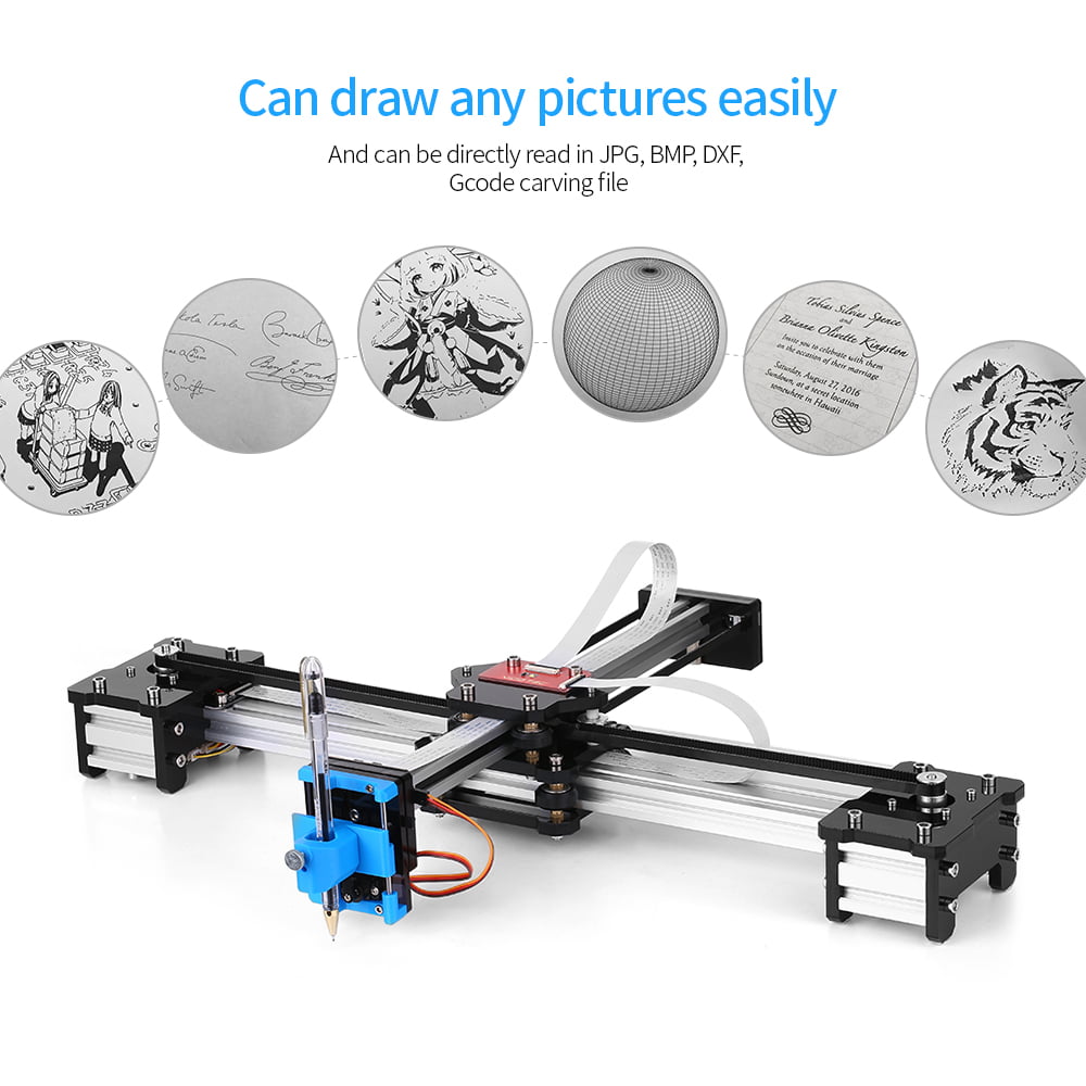
The chess playing robot gets instructed with serial commands, but this is just for the chess playing robots program. It uses a servo to raise and lower a magnet to pull the pieces along, which could easily be replaced with for example a pen. Right now its a chess playing robot, which has one stepper moving the x-axis, and one moving the y-axis. That polargraph device looks very interesting - especially its size capability. If you are content (at least to start with) with monochrome images you could easily use a Python (for example) program to extract start and stop coordinates and penUp/penDown instructions from a 2-colour photo - I.e. It would help if you explain what capability your existing plotter has.


 0 kommentar(er)
